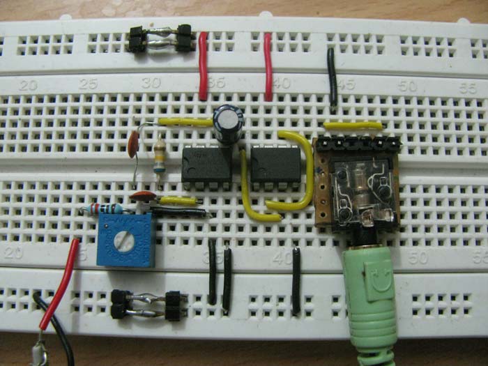
Passive bandpass filters are an essential component of many electronic circuits. They are widely used to filter out unwanted frequencies and amplify desired signals. In this article, we will explore the response and behavior of passive bandpass filters and why they are an important aspect of electronic design.

What is a Passive Bandpass Filter?
A passive bandpass filter is an electronic circuit that selectively allows certain frequencies to pass through while attenuating others. It consists of a combination of resistors, capacitors, and inductors, arranged in specific configurations to achieve the desired frequency response. Unlike active filters, passive filters don't require an external power source, and hence, are often preferred for low-cost and low-power applications.
The Response of Passive Bandpass Filters
The response of a passive bandpass filter is characterized by its center frequency and the bandwidth. The center frequency is the frequency at which the filter offers maximum gain or attenuation, while the bandwidth is the range of frequencies that are allowed to pass through.
The response of a passive bandpass filter is determined by its component values and its configuration. A simple configuration involves a series LC circuit in parallel with a resistor. This configuration is known as a second-order bandpass filter and has a peak in its response centered at the resonant frequency (F_r) = 1 / (2π √L C) and a bandwidth (BW) given by the equation BW = R / 2L.
Another configuration involves using two LC circuits in series with a resistor. This configuration is known as a fourth-order bandpass filter and has a sharper response than the second-order filter. The resonant frequency and bandwidth of this filter can be calculated using the same equations as for the second-order filter.
The Behavior of Passive Bandpass Filters
The behavior of a passive bandpass filter can be understood by analyzing its transfer function. The transfer function is the ratio of the output voltage to the input voltage and represents the filter's frequency response.
The transfer function of a second-order bandpass filter is given by the equation:
H(jω) = R / (R + jωL + 1 / jωC)
where H(jω) is the transfer function, j is the imaginary unit, ω is the angular frequency, R is the resistor value, L is the inductor value, and C is the capacitor value.
The transfer function of a fourth-order bandpass filter is given by the product of two second-order transfer functions.
The behavior of passive bandpass filters can be affected by the loading introduced by other components in the circuit. Loading can occur due to the parasitic capacitances and inductances of other components, such as connecting wires or PCB traces. This loading can shift the resonant frequency and affect the filter's bandwidth.
Conclusion
Passive bandpass filters are an essential component of electronic circuits that allow selective filtering of frequencies. They have a characteristic center frequency and bandwidth determined by their component values and configurations. The behavior of these filters can be influenced by the parasitic capacitances and inductances of other components in the circuit. Understanding the response and behavior of passive bandpass filters is crucial for designing effective electronic circuits.
In conclusion, passive bandpass filters are an important aspect of electronic design, featuring a wide range of applications in various fields. Understanding their behavior and response can help in achieving optimum performance, and hence, they must be given due consideration while designing electronic circuits.